As mentioned in the last post, there was some room for improvement in the last iteration of the trigger/divider circuit. While the divider was working great as a clock source for the drum machine, the signal output by the comparator was very short and sometimes got triggered twice with one acoustic hit on the piezo when the reference voltage was not perfectly tuned. On the other hand the outputs of the 4017 always stay on or off for a whole step.
While the long steps can be useful to make an oscillator play long notes, shorter pulses each step are much more interesting to create drum-ish sounds. Here’s a crude drawing of how what the circuit was doing vs how it’s supposed to work:
The black lines are the signal levels ‘as they used to be’: you can see that the comparator output has very short pulses of more or less random duration, the /2 output is on half of the time, the /3 one third of the steps and so on. Given some way of creating the blue signal in the top diagram, that stays on a specified amount of time after each trigger and only then drops back down, the other two blue graphs are very easy to obtain by simply logical-AND-ing the shaped pulse signal and the divided signal for each divison. Conveniently, there is a CMOS chip with four AND gates that are more than fast enough: the 4081.
hold on
The only missing part is the one that needs to hold the signal for a specified time on each trigger. Well, the famous 555 Timer IC has our back: in the monostable Configuration it will do just that. Here’s a schematic of the basic circuit (pic taken from here):
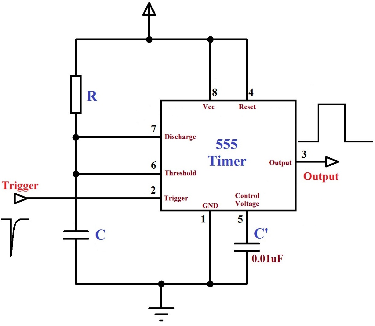
This is really half as bad as it looks, but the details are better read up on elsewhere. Basically, whenever the signal on the trigger (pin 2) goes low, the output (pin 3) goes high and the capacitor between threshold (pin 6) and ground is charged. When it reaches a certain charge, the output drops back to low and the capacitor is drained.
This is exactly what is needed, except that the triggers has to go low here to start the timer. To fix this, I simply swapped the inverting and non-inverting inputs of the comparator, so that it always outputs the opposite result.
putting it together
Here’s the final schematic as I built it:
Some things you may notice:
- I put a potentiometer into the 555s charging path so that the pulse length can be adjusted.
- I added a switch that allows me to decide whether I want to AND the divided outputs with the generated pulse, or basically disable that part by putting 9V there, which basically turns the AND gate into a normal wire.
- There are diodes on the reset pins so that I can later expand this with a reset input jack.
- I am using both halves of the LM393 with the inputs swapped: the positive-going pulse goes to an LED that shows me the ‘raw’ incoming signal, and the negative goes to the 555, with another LED showing the ‘shaped’ one. With piezo triggers it is impossible to even see the raw LED turn on, but if I use this with another clock source (LFO for example) it might be useful.
- We’re kind of low on switches so I scrapped that part, but I wanted another switch to choose between the 555 output or the other LM393 output to be fed into the 4017 dividers. That way I would’ve gotten to keep the beat-skipping properties independently of the gate length control, but now I have to lower the gate length to minimum to disable the 555s debouncing effects.
wrapping it up
After this was all working on the breadboard, I started to solder a second version on stripboard. Before finishing the design I sketched some stripboard layouts on a piece of paper, but in the end I threw all care overboard and just placed components on the stripboard.
I cut apart a large IC socket and soldered the two halfes to the sides of the board to simplify testing and panel wiring, but I’m not sure if it was the best idea bceause the sockets aren’t really made to be used over and over and the wires dont hold too well. I’m thinking I might tape over the sockets once all the cables are in place and tested.
Juan found this great old Video casette case as a chassis and I really liked it. We used the Dremel that we had luckily gotten our hands on and started drilling holes for the audio jacks with a template made from paper.
The inside also needed some plastic spines ground away to make room for the jacks, but the Dremel made quick work of all that. Juan finished the top of the case with mounting holes for the two potentiometers, the input jack, the switch, and two hot-glue-covered holes for the LEDs to shine through.